Introduction
In the late 80’s and early 90’s, we had a video game arcade up the road from where we lived, and I used to go there often and play arcade games.

While gaming technology has moved on, there is still a place for those old classics. The old Nintendo NES console was also popular around the time, and I have a lot of good memories playing games with my friends.
Having purchased some Raspberry PIs a few years ago, I discovered back then that one of the popular projects to use one of these brilliant single board computers for, was to build a retro games console. I stumbled upon the RetroPie platform, which is essentially all the software you need (aside from the ROMs).
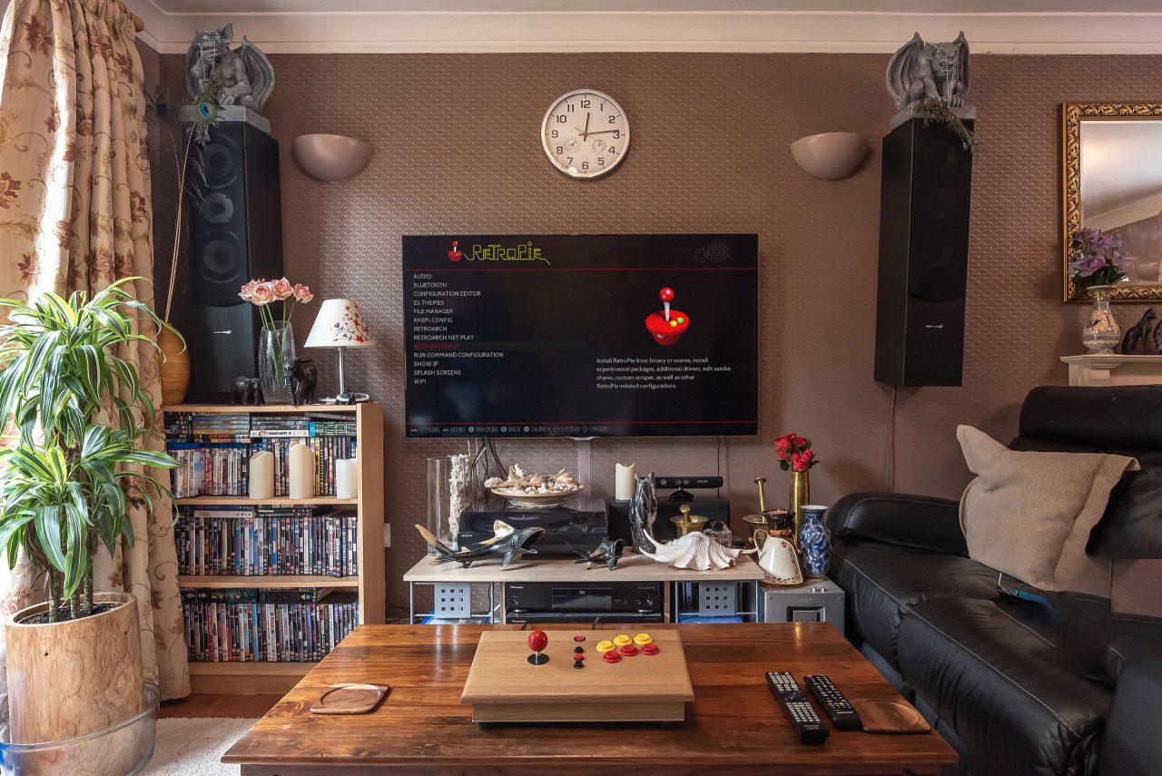
We all have large TVs now, and I didn’t feel the need to build a large fully featured console, but rather wanted something portable which I could connect to my TV. What was important to me was to was to recreate the same playing experience, by using similar controls to the large arcade consoles.
So all I needed was a box large enough to allow me to use the controls as well as house all the electronics and the Raspberry PI.
3D Model
I started out by creating a 3D model of the console, so that I could visualise the layout and ensure all components fit within the enclosure:
3D Viewer Instructions
Mouse Wheel OR Shift + Left Button to Zoom | Left Button to Rotate | Right Button OR Shift + Left Button to Pan
Parts Used

I bought a Sanwa JLF-TP-8YT Ball Top joystick from eBay as well as some mechanical switch pushbuttons, both of which are very similar to what the old arcade machines used.
I realised it would be beneficial to expose the joystick and button functionality as a USB output so that I can also use it with my PC emulator and other games. I found a board that was built for this purpose: the MiniPAC. This board is essentially a programmable keyboard emulator, although it has additional functionality. You connect all the buttons / switches up to it, connect it to USB and then program which keys are activated for the buttons / joystick using WinIPAC software.
Note that many Arduinos can act as a USB host and can be used instead of the MiniPAC. Using the MiniPAC just makes it easier to remap buttons as and when needed, without having to dig out the code much later and try and remember what you did!
Of course you can take it to the extreme and have an LCD display on the console and program a set of menus to allow you to remap the buttons right there on the controller! 😄
And then of course I used a Raspberry PI 3B+ (which was relatively new at the time), with an official 5.1V power supply.
I designed and assembled two circuits, one for powering up and shutting down the Raspberry PI with the push of a button (shutdown controller), and the other for switching the USB signal from the Raspberry PI USB port to an external USB socket for plugging the MiniPAC directly into the PC (USB switcher).
The shutdown controller sends signals to and from the Raspberry PI to orchestrate a graceful shutdown, and simply latches power to it to initiate startup, with a Python script on the Raspberry PI handling the events accordingly.
With the USB switcher, in the absence of power to the Raspberry PI the relay is off, and the MiniPAC USB signal is routed to an output on the back of the unit. When the powered up, the relay energizes and switches the USB signal from the output to the Raspberry PI, so that the MiniPAC is connected directly to the Raspberry PI. This essentially gives the controls to the Raspberry PI and cuts off the rear USB output.
To finish off the build I bought some USB and HDMI panel mount cabled sockets, and an SD card extension, for exposing outputs on the back. I had a mains connector in stock.
Something I was completely unaware of when I built this console was the fact that you can get different ‘restrictor gates’ for the joystick – these are plates that fit underneath the joystick and constrain the movement of it. The most common ones are square, round and octagonal.
Most joysticks are 8-way, so the four directions plus another 4 diagonal directions. This is handled by 4 microswitches, with diagonal directions being detected by two microswitches being engaged at once. These restrictor gates govern how the joystick moves, and different restrictor gates are suited for different games.
For example, Pac-Man only registers up/down/left/right movements. If you hit a diagonal, it just ignores it and you get eaten by a ghost. I learned this the hard way and initially thought something was wrong somewhere! So in this case a rotated square restrictor gate works well by constraining the joystick movement vertically and horizontally.
Here is an ‘interesting’ article and video on all of this: How Arcade Restrictor Gates Work
Restrictor gates:

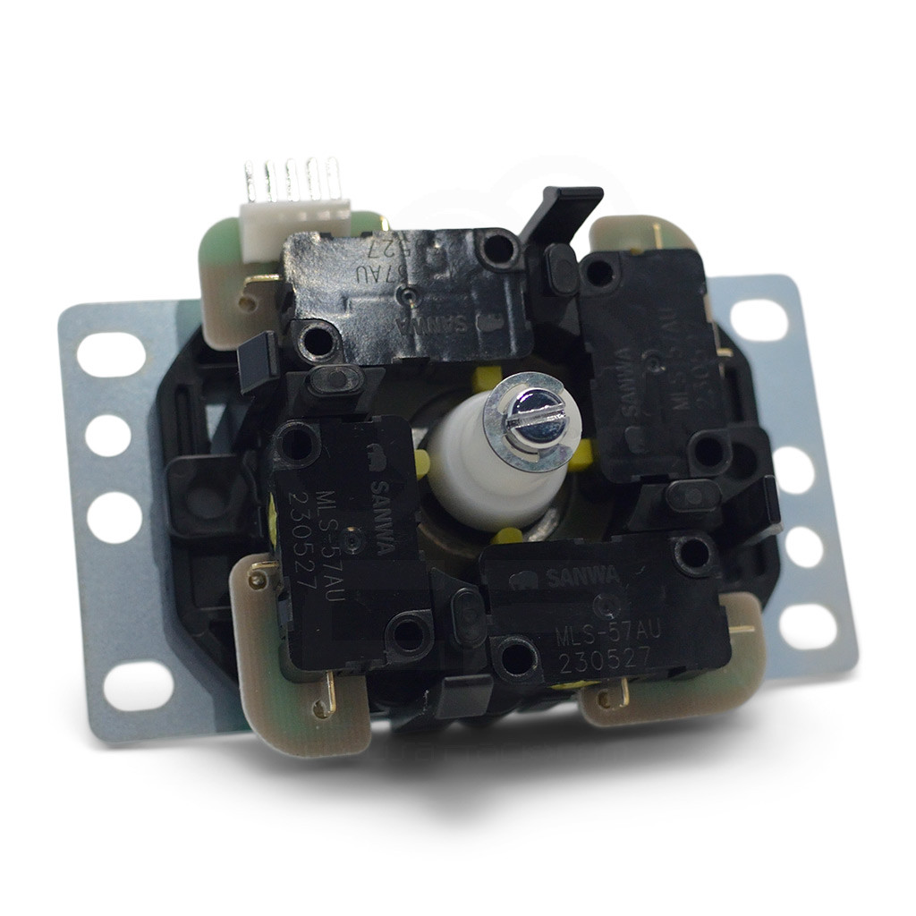
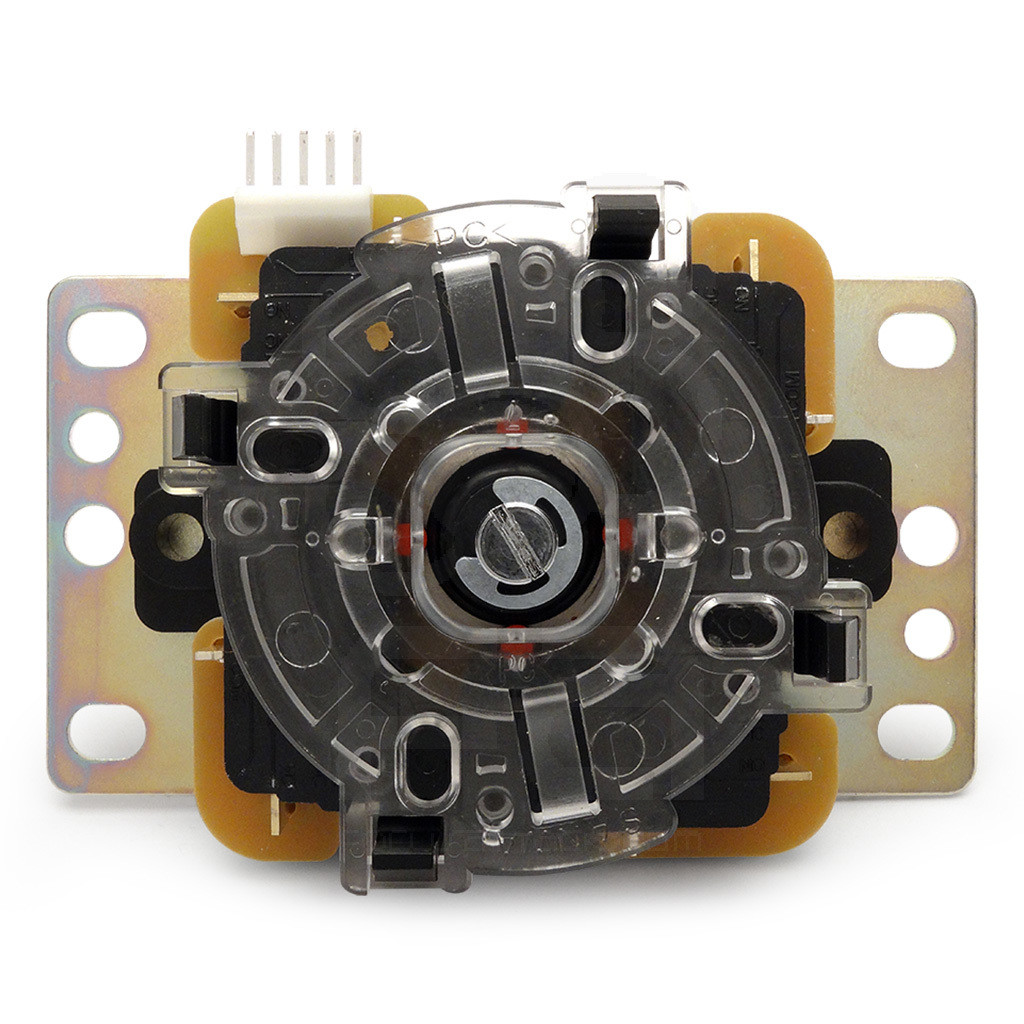
Microswitches inside the Sanwa Joystick
Square restrictor gate on the back
Shutdown Controller
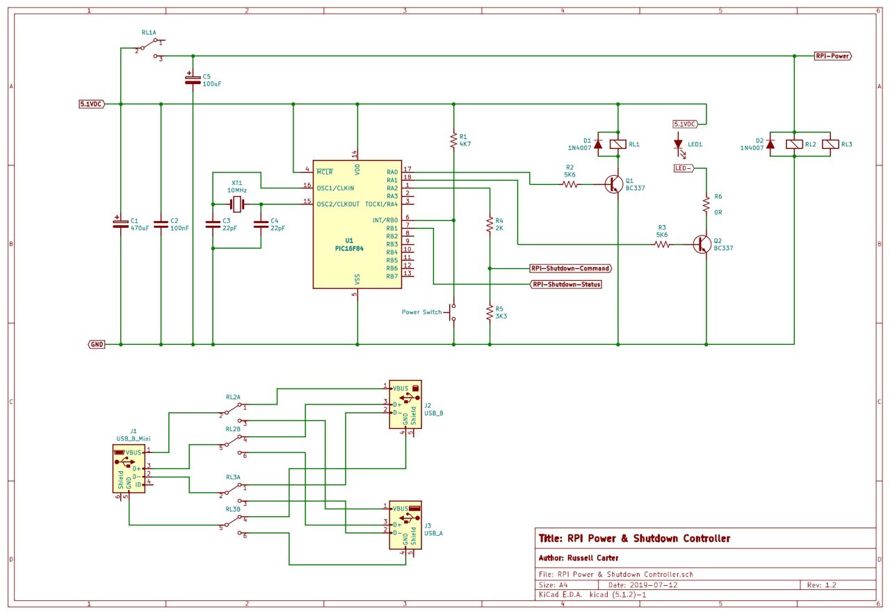
The Raspberry PI cannot simply be switched off. It needs to be powered down gracefully to avoid corruption to the operating system file structure. To make it easy to shutdown the Raspberry PI, I created a circuit to allow a pushbutton to initiate the shutdown sequence, and then power off the Raspberry PI when it was complete.
I created a simple program for a PIC16F84 microcontroller to listen for the button push, and send a signal to a GPIO pin on the Raspberry PI. A Python script on the Raspberry PI (that launches at startup) listens for the signal, and then commences shutdown. Once complete, an overlay configuration sets a GPIO pin high, which then causes the PIC16F84 to switch off the power relay, removing power from the Raspberry PI.
Pressing the power button again simply causes the PIC16F84 to switch the relay on again, latching power to the Raspberry PI, starting the boot sequence normally.
Shutdown controller circuit diagram:
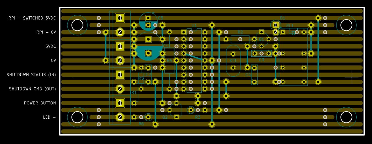
Veroboard layout:
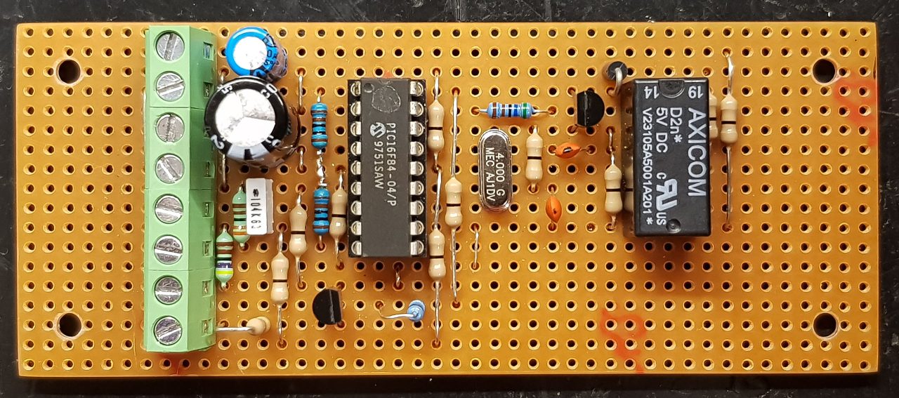
Completed circuit:
Debugging the Assembly Code:
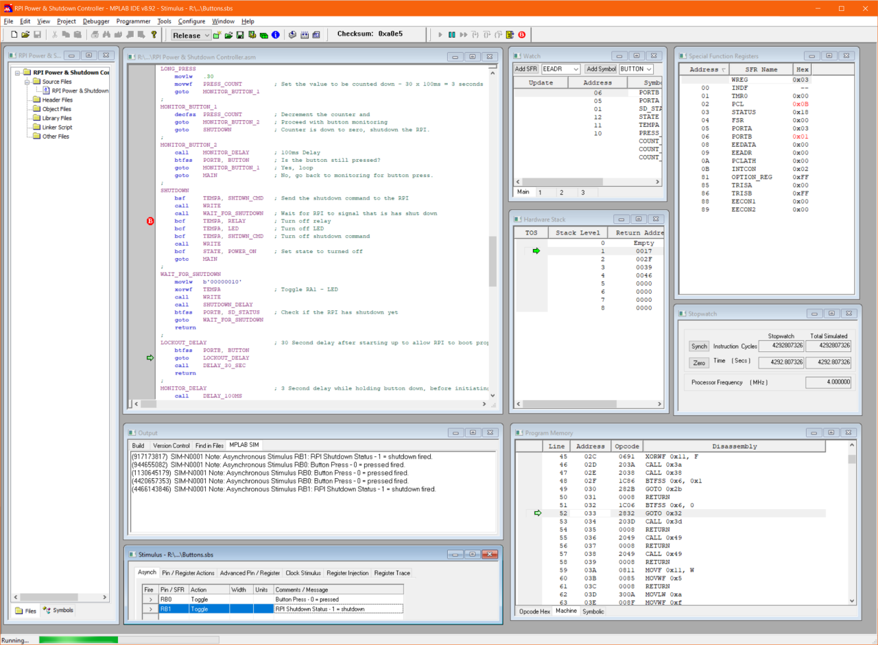
PIC16F84 Assembly code:
ASM;
;   Title:   RPI Power & Shutdown Controller for Retropie Arcade Joystick Console
;   Author:  Russell Carter
;   Date:    18 July 2019
;
    List     P=16F84,F=inhx8m
;   #include p16F84.inc  ; processor specific variable definitions
;
;===========Register Files=======================================================
;
INDF        equ   00
TMR0        equ   01
PCL         equ   02
STATUS      equ   03
FSR         equ   04
PORTA       equ   05
PORTB       equ   06
EEDATA      equ   08
EEADR       equ   09
PCLATH      equ   0A
INTCON      equ   0B
OPTION_REG  equ   81
TRISA       equ   85      ; A "1" sets the relevant port bit as input
TRISB       equ   86      ; A "0" sets the relevant port bit as output
EECON1      equ   88
EECON2      equ   89
;
;===========Status Bits==========================================================
;
IRP         equ   07      ; Not Used
RP1         equ   06      ; Not Used
RP0         equ   05      ; 0 = Bank0, 1 = Bank1
NOT_TO      equ   04      ; WDT Time-out Bit*
NOT_PD      equ   03      ; Power Down Bit*
Z           equ   02      ; 1 = Result is 0
DC          equ   01      ; Digit Carry/Not-Borrow*
C           equ   00      ; 1 = Carry-out from MSB
;
;===========Intcon Bits==========================================================
;
GIE         equ   07      ; 0 = Disables all interrupts
EEIE        equ   06      ; 1 = Enables EE Write complete int
T0IE        equ   05      ; 1 = Enables TMR0 int
INTE        equ   04      ; 1 = Enables RB0/INT int
RBIE        equ   03      ; 1 = Enables RB port change int
T0IF        equ   02      ; 1 = TMR0 has overflowed
INTF        equ   01      ; 1 = RB0/INT int occured
RBIF        equ   00      ; 1 = An RB port pin changed state
;
;===========Option_Reg Bits======================================================
;
NOT_RBPU    equ   07      ; 0 = PortB Pull-ups enabled
INTEDG      equ   06      ; 1 = Int. on rising edge
TOCS        equ   05      ; TMR0 Clk 1 = External: T0CKI
T0SE        equ   04      ; 1 = Inc on falling edge of T0CKI
PSA         equ   03      ; 1 = Prescaler on WDT, 0 = Psa on TMR0
PS2         equ   02      ; Prescaler rate select bits*
PS1         equ   01      ; Prescaler rate select bits*
PS0         equ   00      ; Prescaler rate select bits*
;
;===========Eecon1 Bits==========================================================
;
EEIF        equ   04      ; 1 = Write op. complete (must be cleared)
WRERR       equ   03      ; 1 = Write op. terminated prematurely
WREN        equ   02      ; 1 = Allows write cycles
WR          equ   01      ; 1 = Initiate write (clears automatically)
RD          equ   00      ; 1 = Initiate EEPROM read (clears auto.)
;
;===========Custom Defined Registers (68)========================================
;
;   Usable range: 0Ch to 4Fh
;
COUNT_MS_1  equ   0C      ; 100ms Delay counter
COUNT_MS_2  equ   0D      ; 100ms Delay counter
COUNT_3S    equ   0E      ; 3 Second Delay counter
COUNT_30S   equ   0F      ; 30 Second Delay counter
PRESS_COUNT equ   10      ; Button press counter
TEMPA       equ   11      ; Temp PORTA storage
STATE       equ   12      ; Store the state of the controller
;
;===========Custom Bits==========================================================
;
POWER_ON    equ   00      ; STATE - Status of RPI: 0 = Power off; 1 = Power On
BUTTON      equ   00      ; PORTB - RB0 - Pushbutton: 0 = pressed or contact bounce; 1 = not pressed
SD_STATUS   equ   01      ; PORTB - RB1 - Status from Rasberry PI. 0 = running; 1 (afer booted) = Shutdown
RELAY       equ   00      ; PORTA - RA0 - Relay: 0 = off; 1 = on
LED         equ   01      ; PORTA - RA1 - LED: 0 = off; 1 = on
SHTDWN_CMD  equ   02      ; PORTA - RA2 - Shutdown Command: 0 = off; 1 = on
;
;===========Information==========================================================
;
;   Data format:   Binary   b'MSB...LSB', (Bit7...Bit0)
;   Hex   0x00
;   Decimal   .000
;
;   We need to store PORTA's value in a temp register and perform all operations in that register.
;   When done we write the result to PORTA. This is because a read-modify-write operation on
;   pin RA4 (open collector) will always read 0 if the output is driving an NPN transistor to ground.
;   The voltage in this case on pin RA4 will be the base-emitter voltage, i.e 0.5-0.7v.
;   Wiring: Resistor from +V to base and RA4, emitter to ground.
;
;===========Beginning of Program=================================================
;
   org      0
   goto     INIT                ; Start Vector
;
INIT
   clrf     PORTA               ; Ensure all port A bits are off
   bsf      STATUS, RP0         ; Set bank 1
   clrf     TRISA               ; Set port A to outputs
   movlw    b'11111111'
   movwf    TRISB               ; Set port B to inputs
   bcf      STATUS, RP0         ; Set bank 0
   clrf     PORTA               ; Ensure all port A bits are off
   clrf     TEMPA               ; Clear temp PORTA reg
   clrf     STATE               ; Clear the state reg
;
MAIN
   btfss    PORTB, BUTTON       ; Test bit RB0 - Power button
   goto     BUTTON_PRESS        ; RB0 is low, so the button is currently pressed or in contact bounce
   goto     MAIN                ; Loop
;
BUTTON_PRESS
   btfss    STATE, POWER_ON     ; Check if the RPI is on. If not, turn on.
   goto     TURN_ON
   btfsc    STATE, POWER_ON     ; Check if the RPI is on. If so, check if button is held for 3 seconds
   goto     LONG_PRESS
   goto     MAIN                ; Go back to waiting for button press
;
TURN_ON
   bsf      TEMPA, RELAY        ; Switch on the relay
   bsf      TEMPA, LED          ; Switch on the LED
   call     WRITE               ; Commit the values to port A
   bsf      STATE, POWER_ON     ; Set the power on state to true
   call     LOCKOUT_DELAY       ; Wait for the RPI to boot properly before allowing shutdown.
   goto     MAIN                ; Resume monitoring the switch
;
LONG_PRESS
   movlw    .30
   movwf    PRESS_COUNT         ; Set the value to be counted down - 30 x 100ms = 3 seconds
   goto     MONITOR_BUTTON_1
;
MONITOR_BUTTON_1
   decfsz   PRESS_COUNT         ; Decrement the counter and
   goto     MONITOR_BUTTON_2    ; Proceed with button monitoring
   goto     SHUTDOWN            ; Counter is down to zero, shutdown the RPI.
;
MONITOR_BUTTON_2
   call     MONITOR_DELAY       ; 100ms Delay
   btfss    PORTB, BUTTON       ; Is the button still pressed?
   goto     MONITOR_BUTTON_1    ; Yes, loop
   goto     MAIN                ; No, go back to monitoring for button press.
;
SHUTDOWN
   bsf      TEMPA, SHTDWN_CMD   ; Send the shutdown command to the RPI
   call     WRITE
   call     WAIT_FOR_SHUTDOWN   ; Wait for RPI to signal that it has shut down
   bcf      TEMPA, RELAY        ; Turn off relay
   bcf      TEMPA, LED          ; Turn off LED
   bcf      TEMPA, SHTDWN_CMD   ; Turn off shutdown command
   call     WRITE
   bcf      STATE, POWER_ON     ; Set state to turned off
   goto     MAIN
;
WAIT_FOR_SHUTDOWN
   movlw    b'00000010'
   xorwf    TEMPA               ; Toggle RA1 - LED
   call     WRITE
   call     SHUTDOWN_DELAY
   btfss    PORTB, SD_STATUS    ; Check if the RPI has shutdown yet
   goto     WAIT_FOR_SHUTDOWN
   return
;
LOCKOUT_DELAY                   ; 30 Second delay after starting up to allow RPI to boot properly
   btfss    PORTB, BUTTON
   goto     LOCKOUT_DELAY
   call     DELAY_30_SEC
   return
;
MONITOR_DELAY                   ; 3 Second delay while holding button down, before initiating shutdown
   call     DELAY_100MS
   return
;
SHUTDOWN_DELAY                  ; 100Ms delay, which is the time between toggling the flashing LED,
                                ; waiting for shutdown to complete
   call     DELAY_100MS
   return
;
WRITE                           ; Write the value to Port A
   movf     TEMPA, 0
   movwf    PORTA
   return
;
DELAY_30_SEC                    ; 30 Second delay
   movlw    .10
   movwf    COUNT_30S
DELAY_30_SEC_LOOP
   call     DELAY_3_SEC
   decfsz   COUNT_30S
   goto     DELAY_30_SEC_LOOP
   return
;
DELAY_3_SEC                     ; 3 Second delay - currently UNUSED
   movlw    .30
   movwf    COUNT_3S
DELAY_3_SEC_LOOP
   call     DELAY_100MS
   decfsz   COUNT_3S
   goto     DELAY_3_SEC_LOOP
   return
;
DELAY_100MS                     ; 100Ms delay
   movlw    .30
   movwf    COUNT_MS_1
   movlw    .79
   movwf    COUNT_MS_2
DELAY_100MS_LOOP
   decfsz   COUNT_MS_1
   goto     $+2
   decfsz   COUNT_MS_2
   goto     DELAY_100MS_LOOP
   nop
   nop
   nop
   return
;
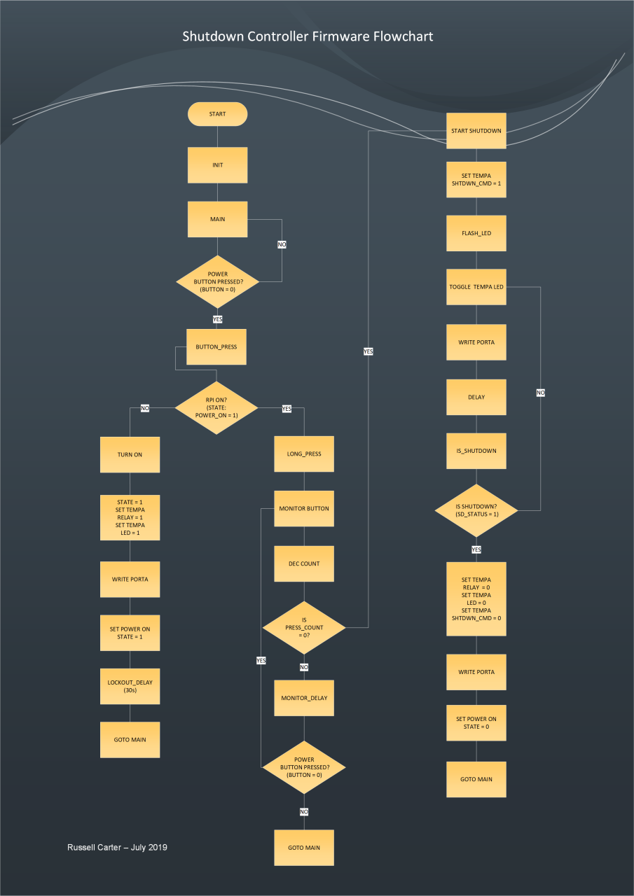
endPIC16F84 Firmware Flowchart:
Python script:
import RPi.GPIO as GPIO
import time
import subprocess

GPIO.setwarnings(False)
GPIO.setmode(GPIO.BCM)
GPIO.setup(20, GPIO.IN, pull_up_down=GPIO.PUD_DOWN)

while True:
    if GPIO.input(20) == GPIO.HIGH:
        print("Pushed")
        subprocess.call("sudo shutdown -h now", shell=True)
    time.sleep(0.5)
To ensure this runs on startup I added a line to the /etc/rc.local file as follows:
sudo python /home/pi/gpio_shutdown.py &For the overlay configuration, edit /boot/config.txt and add:
dtoverlay=gpio-poweroff,gpiopin=21Box Construction
For the construction of the box I used an old solid oak cupboard door.
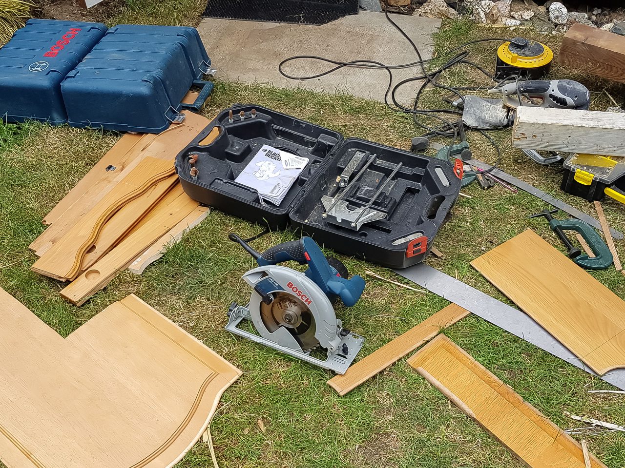
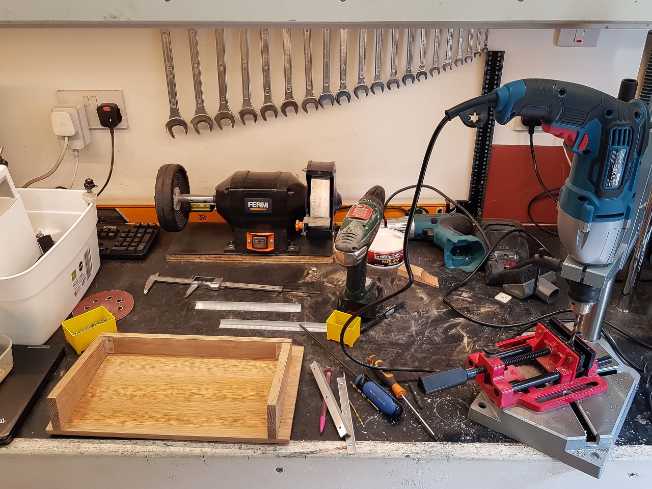
It was not my intention to create a woodworking masterpiece, so I assembled the unit using aluminium brackets to hold all the sides together.
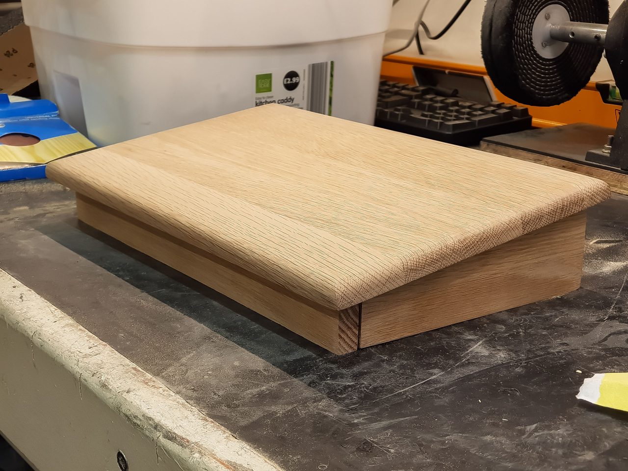
I did want it to look good however, so I gave the playing surface a nice rounded edge and sanded it down to a smooth finish, before applying 3 coats of wood varnish.
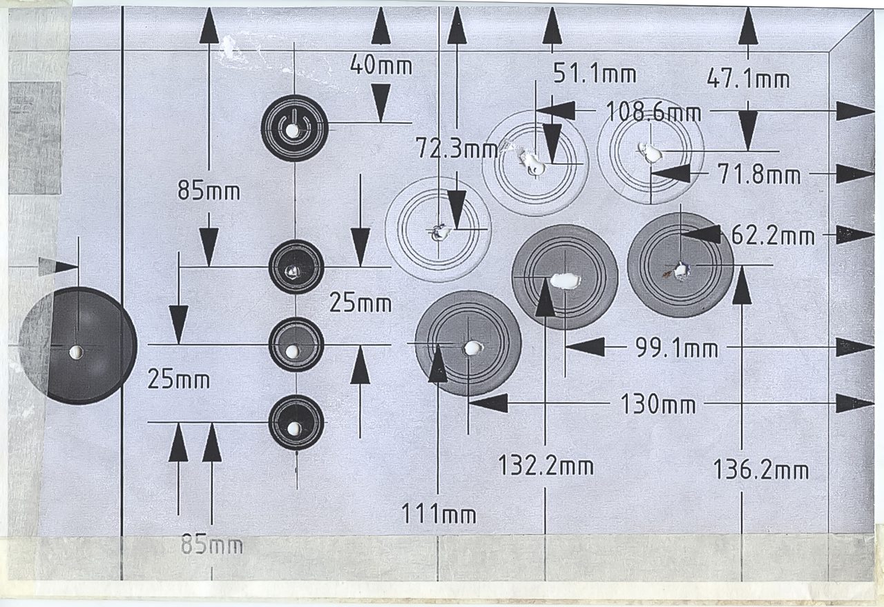
I designed the layout on the PC and printed it to scale, and stuck it onto the surface to act as a guide for drilling the holes.
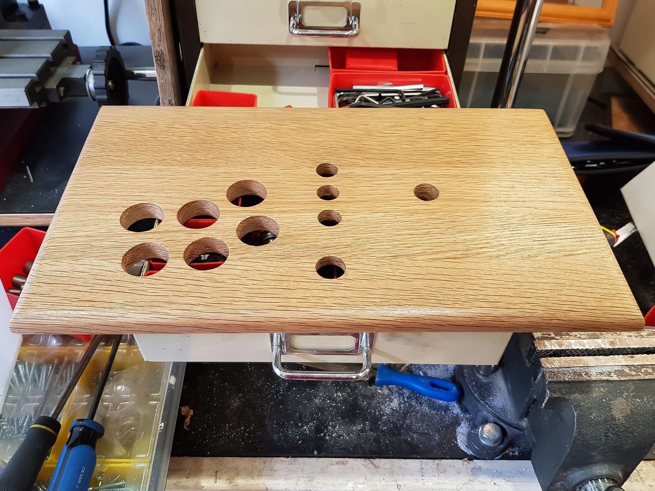
Forstner bits were used to drill the holes to keep them as neat as possible.
Internal Construction & Wiring
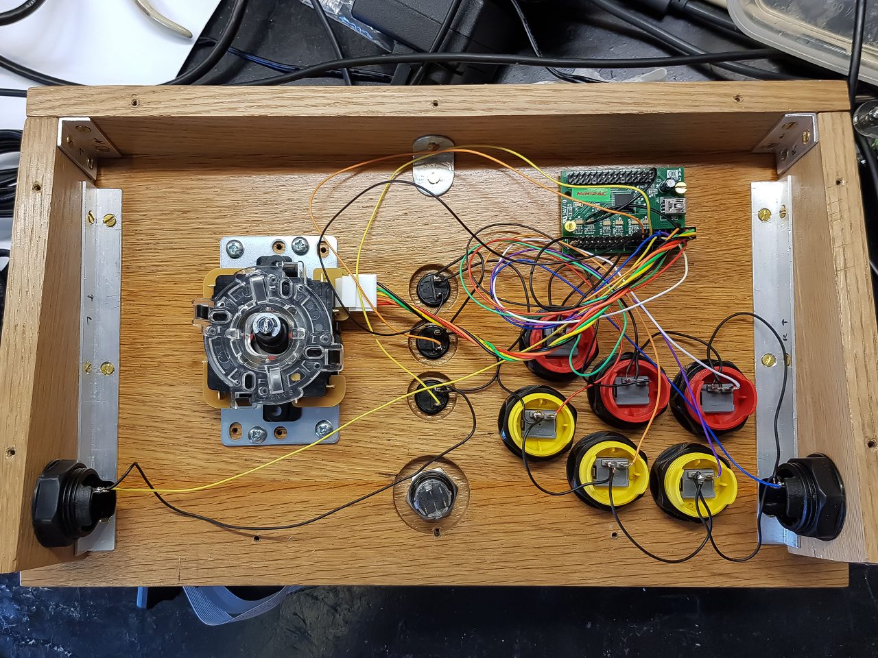
The joystick and buttons were fitted and used to test and program the MiniPAC:
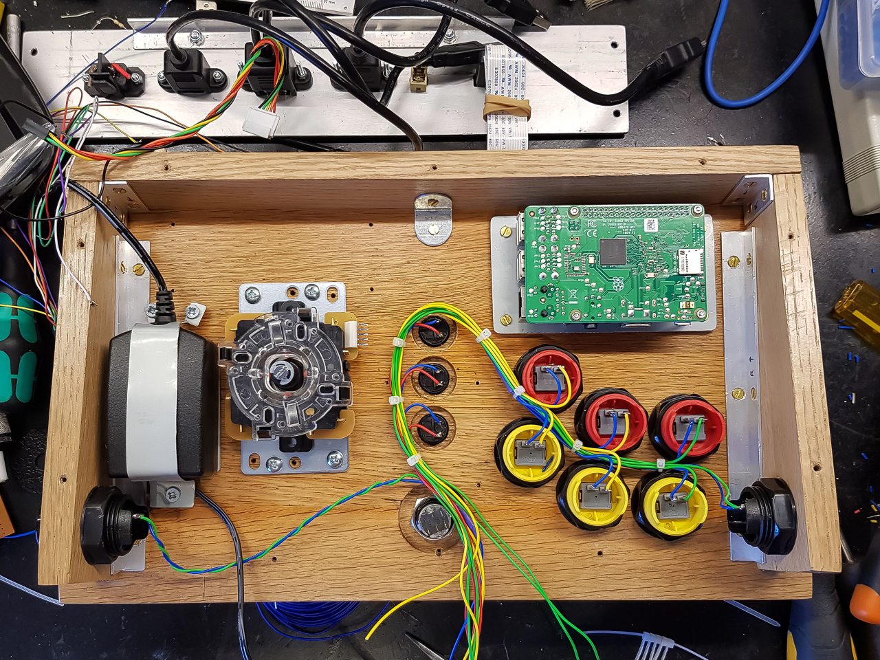
Next I mounted the Raspberry PI and it’s power supply, and started creating a wire harness to keep the wiring neat and tidy. I made a metal bracket to hold the Raspberry PI power supply, and mounted the external cabled sockets to the 3mm aluminium back plate:
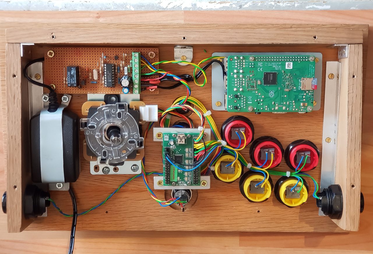
After that I mounted and wired up the shutdown controller circuit and MiniPAC:
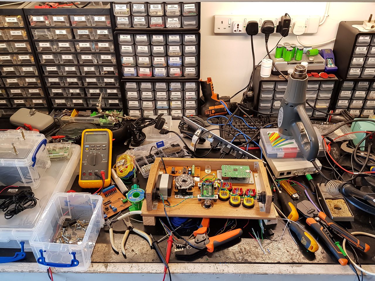
Assembling the console on my electronics bench:
Insertion of the USB switcher board and wiring up of the external cabled sockets:
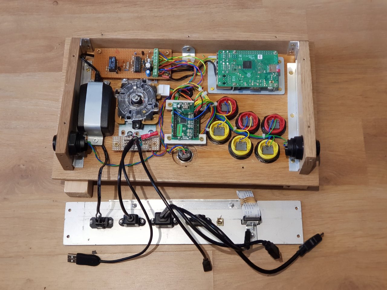
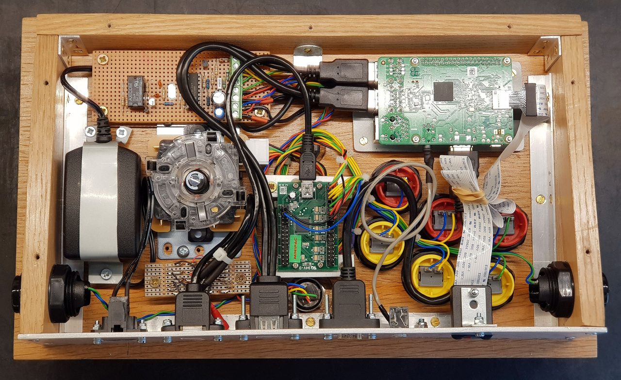
All cables neatly stuffed in, ready for closing. I used another 3mm aluminium plate for the bottom, with four large rubber feet fitted:
MiniPAC Configuration
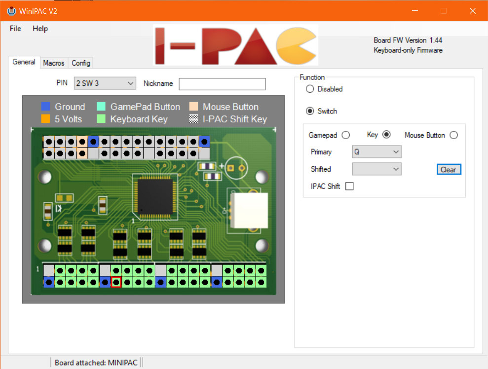
I found that the most sensible approach to key mapping was to map keys for the different functions in RetroPie to sensible keys on the keyboard. After that I programmed the buttons connected to the MiniPAC to these keys.
Key mapping the MiniPAC button pins to keys is done in WinIPAC. MiniPAC > WinIPAC 😄
Software
This is an important ingredient, along with the game ROMs themselves, of course. I chose RetroPie, because it is a complete solution, and comes as a pre-made image for the Raspberry Pi. The RetroPie SD image comes pre-installed with many different emulators. Additional emulators may be installed from within RetroPie.
Note that you need to find and download game ROMs before you can actually play any games. There are websites that allow you to download legal ROMs, and also websites that distribute illegal ROMs. I only use legal ROMs of course.
EmulationStation is the official graphical frontend of the RetroPie project. It’s not an emulator itself – it’s a game launcher that includes controller and keyboard support, and custom themes.
Incidentally there is a Windows / Mac / Linux desktop version called ES-DE.
It’s worth noting that RetroPie supports many different types of controllers, including the Xbox Wireless Controller (Bluetooth) which I have. You can therefore simply install RetroPie on a bare Raspberry Pi and connect to it with a controller, or keyboard even.
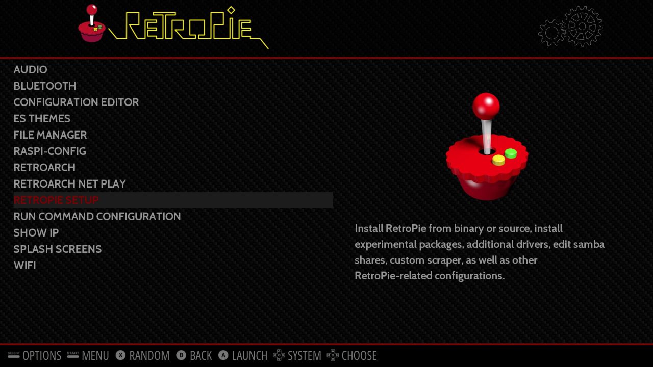
This video by NetworkChuck takes you through the installation process of RetroPie if you are interested in doing this:
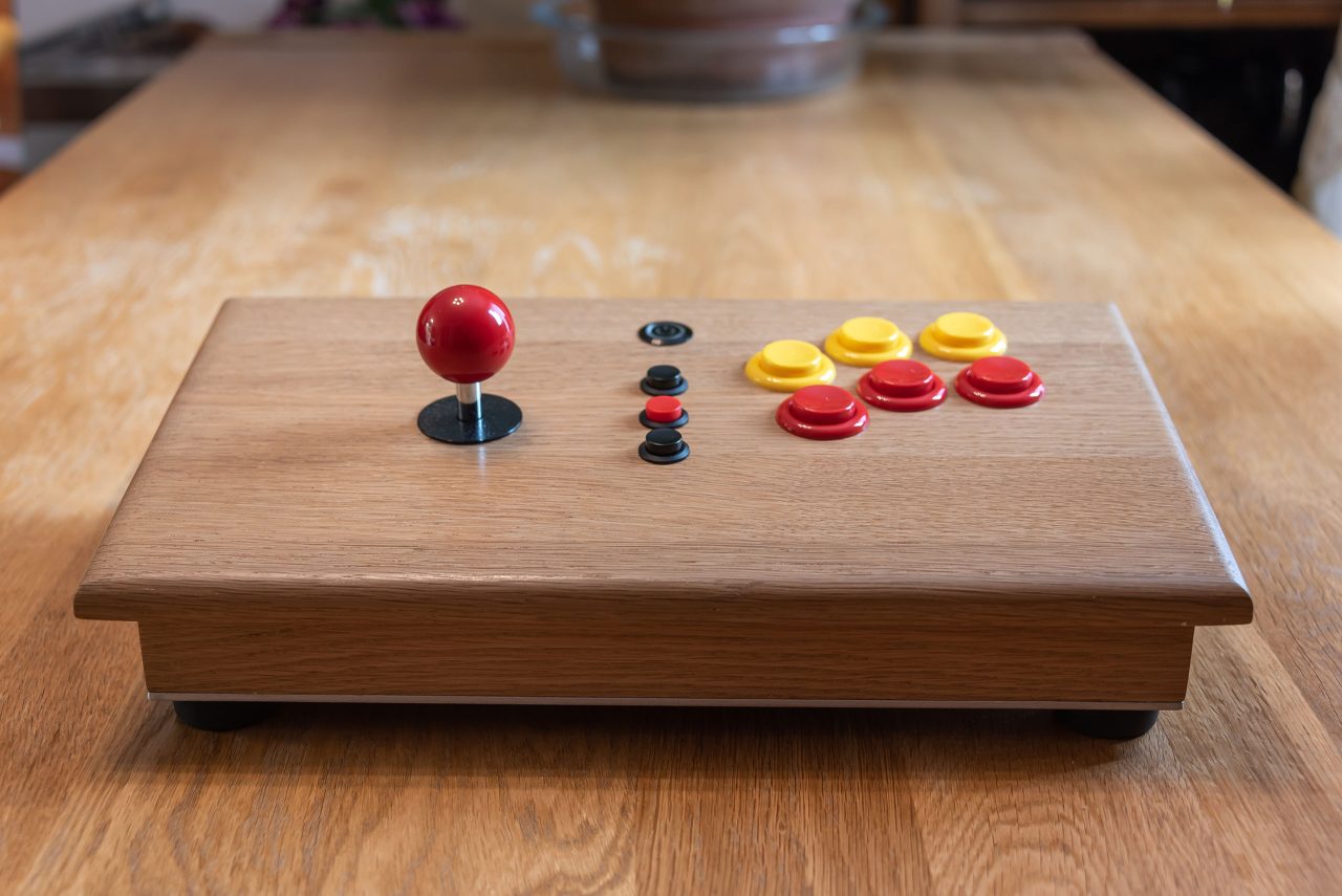
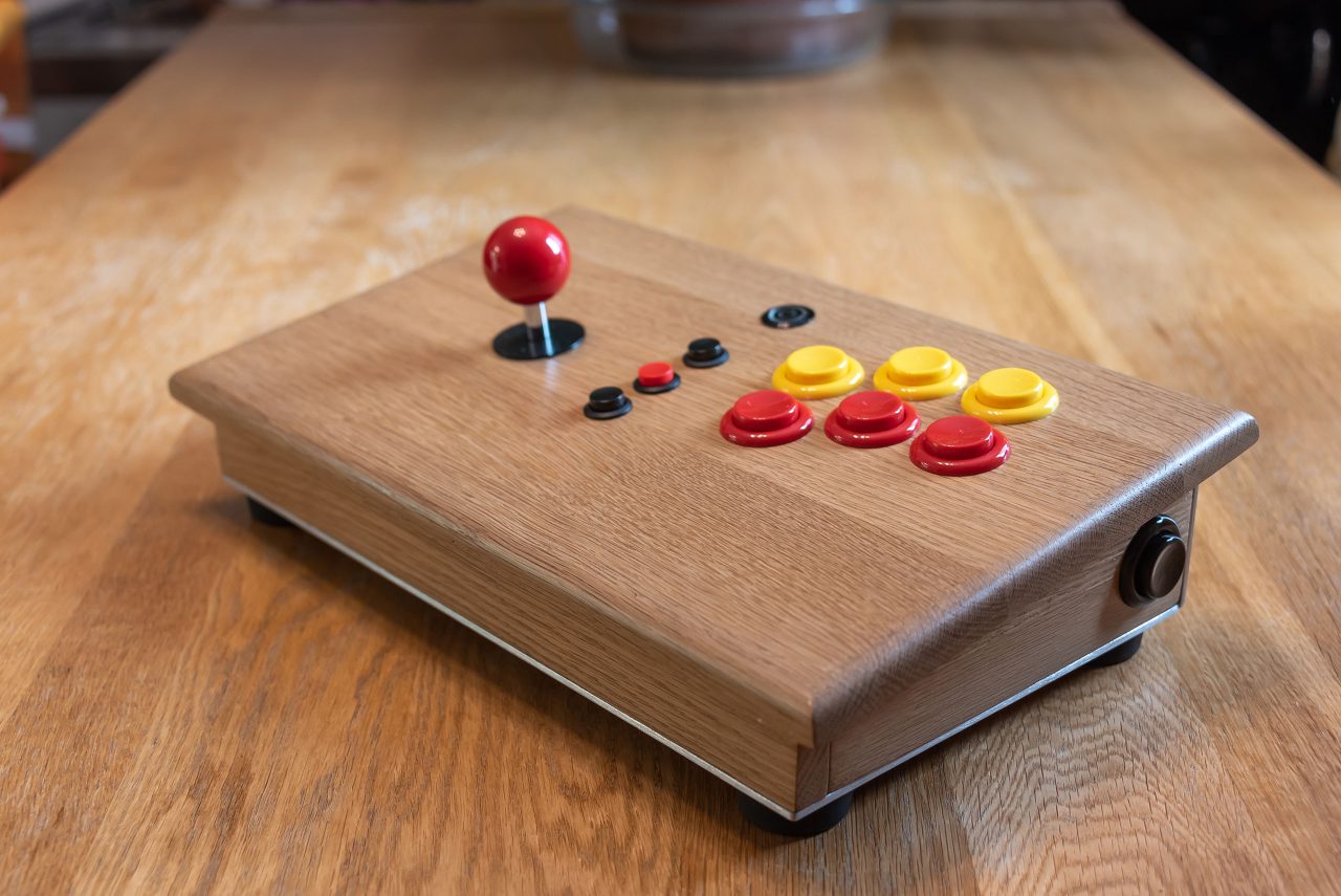
Final Product
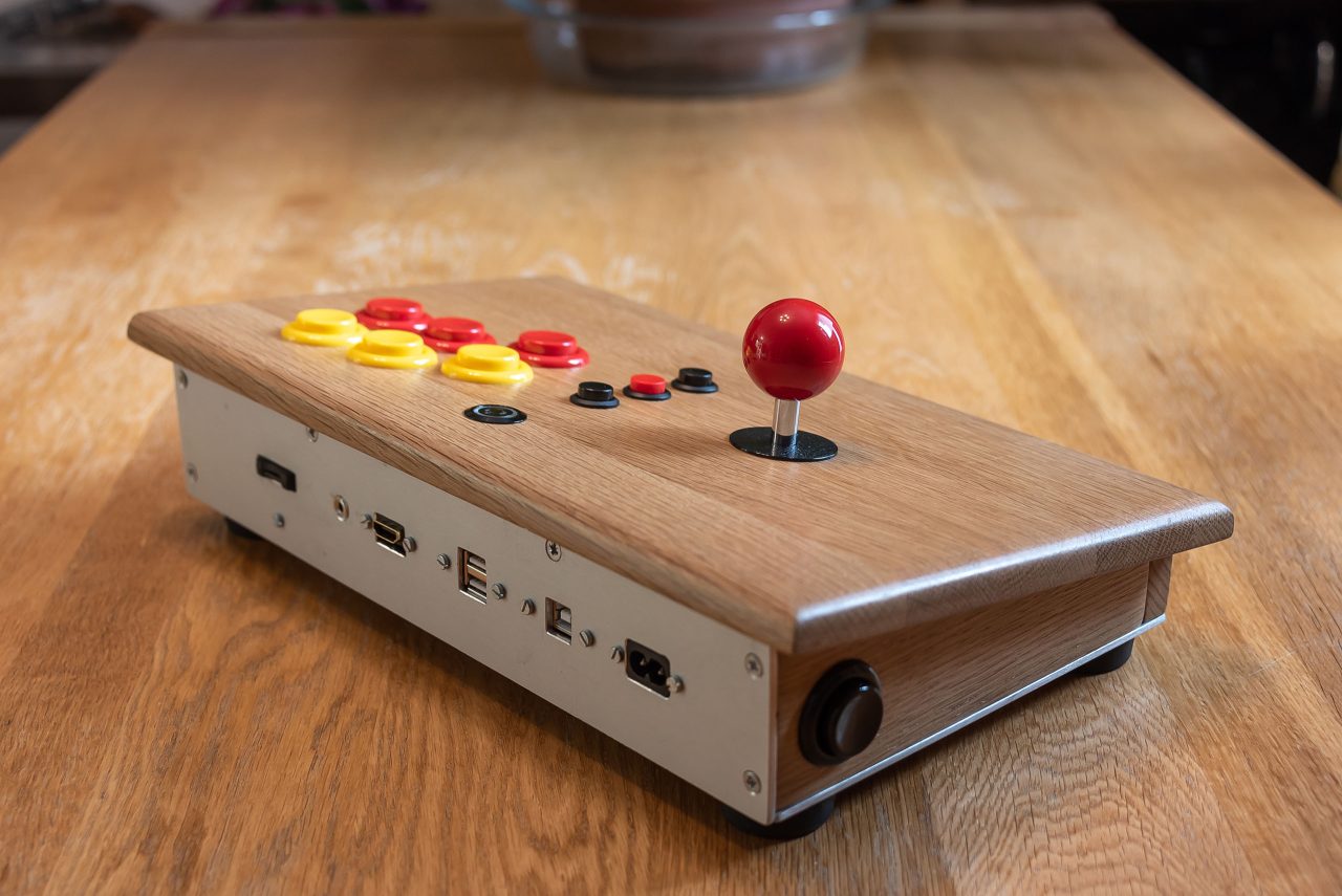
The rear panel exposes the following connections:
- 240V Input socket
- Printer style Type B USB socket for connecting the MiniPAC to the PC
- 2 USB-A 2.0 ports for a keyboard and mouse – connect directly to the Raspberry PI
- HDMI out socket
- Headphone socket
- SD Card socket
Leave a Reply