Introduction
In the 90s I worked as an electronics design engineer for a small company that supplied rechargeable batteries, battery packs, power supplies and chargers.
The client base included individuals, small and large companies, the hobby industry, the emergency lighting industry, mobile phone providers, the Ministry of Defence, Post Office, and Prison Services.
One particular client in the hobby industry commissioned us to build a multifunction charger that could charge, discharge, and perform load testing on NiCd (nickel–cadmium) battery packs.
Design
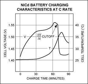
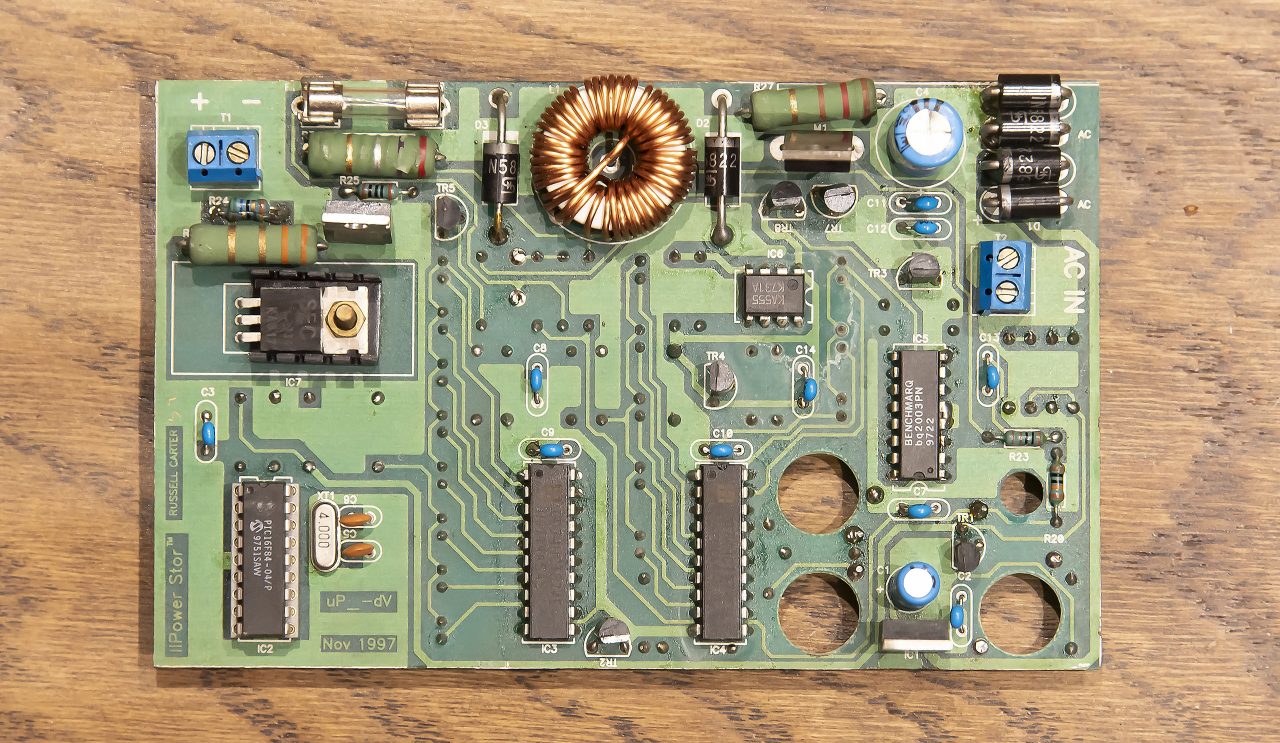
I had built a number of charging systems around the bq2003PN IC, a fast charge IC with with high-speed switching power control circuitry (PWM). It detects a negative delta voltage (-ΔV) in the battery’s charge curve to terminate fast charge:
I chose the Microchip PIC16F84 microcontroller to control the charge circuitry and allow the user to set a charge / discharge cycle and view the status on the front panel. These were very popular back then, specifically the ones that use flash memory, which allows the device to be reprogrammed multiple times. We take this for granted now with the Arduino and other devices, but back then it was a brilliant concept and allowed for easy iterative development.
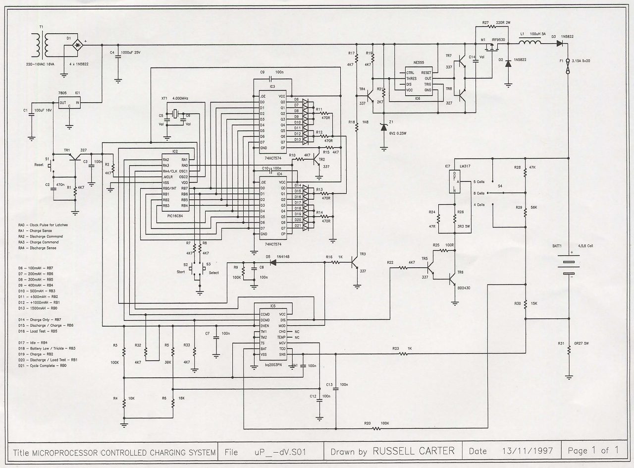
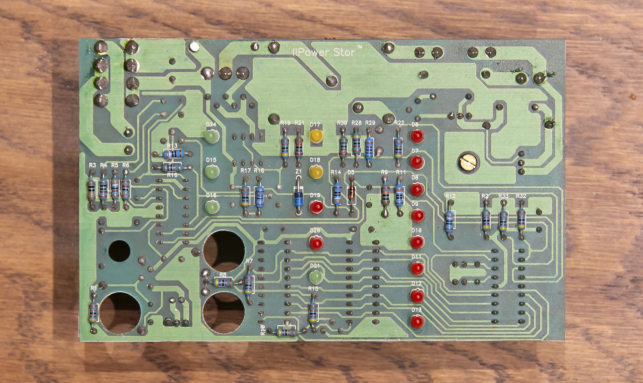
The power fast charging circuit consists of a 555 driving a MOSFET via PNP / NPN transistors in a standard buck configuration. The PWM signal is provided by the bq2003PN. Discharge is via an LM317 in constant current mode. The LEDs are latched using 74HCT574 D-type tristate flip flops.
Firmware
The PIC16C84 firmware was written in Assembly language, and is listed below:
; uP Controlled -dV Fast Charger - Copyright © Russell Carter 01/1998
;
    List    P=16C84,F=inhx8m
;
tmr0          equ    01
pcl           equ    02
status        equ    03
porta         equ    05
portb         equ    06
eedata        equ    08
eeadr         equ    09
intcon        equ    0B
options       equ    81
trisa         equ    85
trisb         equ    86
eecon1        equ    88
eecon2        equ    89
count_1       equ    0C        ; Second divider
count_2       equ    0D        ; Second divider
lt_latch      equ    0E        ; IC3 : D7 - D0
sc_latch      equ    0F        ; IC4 : D7 - D0
del_1         equ    10        ; Delay reg 1
del_2         equ    11        ; Delay reg 2
flags         equ    12        ; Flag register
sec           equ    13        ; Seconds register
min           equ    14        ; Minutes register
table         equ    15        ; Next table read location
del_mult      equ    16        ; Delay Multiplier
;
    org       0
    goto      init_ports       ; Start
    nop
    nop
    nop
    goto      service_int      ; Interrupt Vector
init_ports
    movlw     b'00001000'      ; RA3 - CCMD held high
    movwf     porta
    clrf      portb            ; Clear Port B
    bsf       status,5
    clrf      trisb            ; Port B set for outputs
    movlw     b'00010010'      ; RA1, RA4 Set for inputs
    movwf     trisa
    bcf       status,5
init_timer
    movlw     .250
    movwf     count_1          ; 2ms Interrupt x 250 = 500ms
    movlw     .2
    movwf     count_2          ; 500ms x 2 = 1000ms = 1 second
    movlw     .60
    movwf     sec              ; 1s x 60 = 1min
    movlw     .15
    movwf     min              ; 15min timeout for 100mAH @ 400mA discharge
    movlw     .10
    movwf     del_mult         ; Multiply delay by 10
init_table
    movlw     .36              ; Last value on the table
    movwf     table
led_test
    movlw     0XFF
    movwf     sc_latch
    movwf     lt_latch         ; Set all LED's
    call      latch_write
    call      med_delay
    call      med_delay
    call      med_delay
    clrf      lt_latch
    movlw     b'10010000'
    movwf     sc_latch         ; Set Idle and Charge Only LED's
    call      latch_write
key_input
    bsf       status,5
    bcf       options,7        ; Enable weak pullups on Port B
    movlw     b'11000000'
    movwf     trisb            ; Set RA7 & RA6 inputs
    bcf       status,5
scan
    btfss     portb,7
    goto      start
    btfss     portb,6          ; Determine which key is pressed
    call      togl_cycle
    goto      key_input
togl_cycle
    bsf       status,5
    bsf       options,7        ; Disable weak pullups on Port B
    clrf      trisb            ; Set RA7 & RA6 outputs
    bcf       status,5
    bcf       sc_latch,4       ; Toggle the Cycle LED's
    rrf       sc_latch
    bcf       sc_latch,7
    btfsc     sc_latch,4
    goto      next
    bsf       sc_latch,4
    call      latch_write
    call      med_delay
    return
next
    movlw     b'10010000'
    movwf     sc_latch
    call      latch_write
    call      med_delay
    return
start
    btfss     portb,6          ; Test for "Old Load Test Value" request
    call      disp_lt
    bsf       status,5
    bsf       options,7        ; Disable weak pullups on Port B
    clrf      trisb            ; Set RA7 & RA6 outputs
    bcf       status,5
    btfsc     sc_latch,7       ; Determine which Cycle is required
    goto      ch_only
    btfsc     sc_latch,6
    goto      dis_charge
    goto      load_test
ch_only
    bcf       porta,3          ; Charge Command
    call      short_delay
    bsf       porta,3
    call      charge           ; Fast Charge
    bcf       sc_latch,2
    bsf       sc_latch,0       ; Set the Cycle Complete LED
    call      latch_write
    goto      cycle_complete
dis_charge
    bsf       porta,2          ; Discharge Command
    call      short_delay
    bcf       porta,2
    call      discharge        ; Discharge
    call      charge           ; Fast Charge
    bcf       sc_latch,1
    bsf       sc_latch,0       ; Set the Cycle Complete LED
    call      latch_write
    goto      cycle_complete
load_test
    movlw     .1
    movwf     eeadr
    movlw     .0
    call      ee_write
    bcf       porta,3          ; Charge Command
    call      short_delay
    bsf       porta,3
    call      charge           ; Fast Charge
    bsf       sc_latch,2       ; Set Charge LED
    call      latch_write
    call      lt_delay         ; Rest battery 5 min before Load Test
    bsf       porta,2          ; Discharge Command
    call      short_delay
    bcf       porta,2
check_1
    btfss     porta,4          ; Wait for Discharge signal
    goto      check_1
    bcf       sc_latch,2       ; Clear Fast Charge LED
    bsf       sc_latch,1       ; Set Discharge LED
    call      latch_write
init_interrupts
    bsf       status,5
    movlw     b'11010010'      ; Set Timer 0: Internal and Prescaler 1:8
    movwf     options
    movlw     b'10100000'      ; Enable Interrupts
    movwf     intcon
    bcf       status,5
wait
    btfsc     porta,4          ; Test for end of Discharge
    goto      wait             ; Wait for Interrupt or end of Discharge
    bsf       status,5
    clrf      intcon           ; Disable Interrupts
    bcf       status,5
    movlw     .1
    movwf     eeadr
    movf      lt_latch,0
    call      ee_write
    call      charge
    bsf       sc_latch,0       ; Set Complete LED
    call      latch_write
    goto      cycle_complete
charge
    bcf       sc_latch,1       ; Clear all Status LED's, Set Batt Low / Trickle LED
    bcf       sc_latch,2
    bcf       sc_latch,4
    bsf       sc_latch,3
    call      latch_write
check_2
    btfss     porta,1          ; Wait for Fast Charge signal
    goto      check_2
    bcf       sc_latch,3       ; Clear Batt Low LED, Set Fast Charge LED
    bsf       sc_latch,2
    call      latch_write
check_3
    btfsc     porta,1          ; Wait for Fast Charge Complete signal
    goto      check_3
    bcf       sc_latch,2       ; Clear Fast Charge LED
    call      latch_write
    return
discharge
    btfss     porta,4          ; Wait for Discharge signal
    goto      discharge
    bcf       sc_latch,2       ; Clear all Status LED's, Set Discharge LED
    bcf       sc_latch,3
    bcf       sc_latch,4
    bsf       sc_latch,1
    call      latch_write
check_4
    btfsc     porta,4          ; Wait for end of Discharge signal
    goto      check_4
    bcf       sc_latch,1       ; Clear Discharge LED
    call      latch_write
    return
service_int
    nop
    nop
    movlw     .07
    movwf     tmr0
    decfsz    count_1          ; Decrement counters for timing
    goto      ret
    movlw     .250
    movwf     count_1
    decfsz    count_2
    goto      ret
    movlw     .2
    movwf     count_2
    call      dec_sec
ret
    movlw     b'10100000'
    movwf     intcon
    retfie
dec_sec
    decfsz    sec              ; Decrement seconds register
    return
    movlw     .60
    movwf     sec
    call      dec_min
    return
dec_min
    decfsz    min              ; Decrement minutes register
    return
    movlw     .15
    movwf     min
    btfsc     flags,0
    goto      dis_int
    call      togl_lt
    return
dis_int
    bsf       status,5
    clrf      intcon           ; Disable Interrupts
    bcf       status,5
    bcf       flags,0
    retfie
togl_lt
    movlw     .0               ; Toggle to next load test value
    addwf     table,0
    btfss     status,2         ; Check for table limit
    decf      table
    movf      table,0
    call      table_1
    movwf     lt_latch
    call      latch_write
    return
lt_delay
    bsf       flags,0
    movlw     .5
    movwf     min
    bsf       status,5
    movlw     b'11010010'      ; Set Timer 0: Internal and Prescaler 1:8
    movwf     options
    movlw     b'10100000'      ; Enable Interrupts
    movwf     intcon
    bcf       status,5
check_5
    btfsc     flags,0
    goto      check_5
    return
table_1
    addwf     pcl
    retlw     b'11111111'      ; Out of Range
    retlw     b'00001111'      ; 3500 mAh
    retlw     b'00010111'      ; 3400 mAh
    retlw     b'00100111'      ; 3300 mAh
    retlw     b'01000111'      ; 3200 mAh
    retlw     b'10000111'      ; 3100 mAh
    retlw     b'00001011'      ; 3000 mAh
    retlw     b'00010011'      ; 2900 mAh
    retlw     b'00100011'      ; 2800 mAh
    retlw     b'01000011'      ; 2700 mAh
    retlw     b'10000011'      ; 2600 mAh
    retlw     b'00001101'      ; 2500 mAh
    retlw     b'00010101'      ; 2400 mAh
    retlw     b'00100101'      ; 2300 mAh
    retlw     b'01000101'      ; 2200 mAh
    retlw     b'10000101'      ; 2100 mAh
    retlw     b'00001001'      ; 2000 mAh
    retlw     b'00010001'      ; 1900 mAh
    retlw     b'00100001'      ; 1800 mAh
    retlw     b'01000001'      ; 1700 mAh
    retlw     b'10000001'      ; 1600 mAh
    retlw     b'00001010'      ; 1500 mAh
    retlw     b'00010010'      ; 1400 mAh
    retlw     b'00100010'      ; 1300 mAh
    retlw     b'01000010'      ; 1200 mAh
    retlw     b'10000010'      ; 1100 mAh
    retlw     b'00001100'      ; 1000 mAh
    retlw     b'00010100'      ; 900 mAh
    retlw     b'00100100'      ; 800 mAh
    retlw     b'01000100'      ; 700 mAh
    retlw     b'10000100'      ; 600 mAh
    retlw     b'00001000'      ; 500 mAh
    retlw     b'00010000'      ; 400 mAh
    retlw     b'00100000'      ; 300 mAh
    retlw     b'01000000'      ; 200 mAh
    retlw     b'10000000'      ; 100 mAh
latch_write
    movf      sc_latch,0
    movwf     portb
    bsf       porta,0          ; Latch Port B into IC4 - Status, Cycle
    movf      lt_latch,0
    movwf     portb
    bcf       porta,0          ; Latch Port B into IC3 - Load Test
    return
disp_lt
    bsf       status,5
    bsf       options,7        ; Disable weak pullups on Port B
    clrf      trisb            ; Set RA7 & RA6 outputs
    bcf       status,5
    clrf      sc_latch
    clrf      lt_latch
    call      latch_write
    call      ee_read          ; Displays the previous value of the load test
    movwf     lt_latch
    call      latch_write
    goto      cycle_complete
med_delay
    call      short_delay
    call      short_delay
    call      short_delay
    return
short_delay                    ; Total Delay = V1(3*V2+8)+6
    movlw     .244             ; Value 1
    movwf     del_1
loop_1
    call      delay_2          ; Values chosen for 100ms
    decfsz    del_1
    goto      loop_1
    return
delay_2
    movlw     .134             ; Value 2
    movwf     del_2
loop_2
    decfsz    del_2
    goto      loop_2
    return
ee_read
    movlw     .1               ; EEPROM Read
    movwf     eeadr
    bsf       status,5
    bsf       eecon1,0
    bcf       status,5
    movf      eedata,w
    return
ee_write
    movwf     eedata           ; EEPROM Write
    bsf       status,5
    bsf       eecon1,2
    movlw     0x55
    movwf     eecon2
    movlw     0xAA
    movwf     eecon2
    bsf       eecon1,1
    bcf       status,5
    call      wr_delay
    retlw     .0
wr_delay
    bsf       status,5         ; EEPROM Write complete detect
    btfss     eecon1,4
    goto      wr_delay
    bcf       eecon1,4
    bcf       status,5
    return
cycle_complete
    goto      cycle_complete
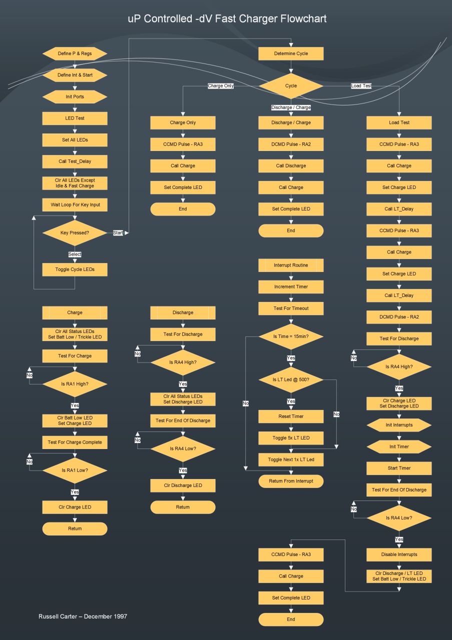
endThe flowchart describes the process controlled by the PIC16C84:
Construction
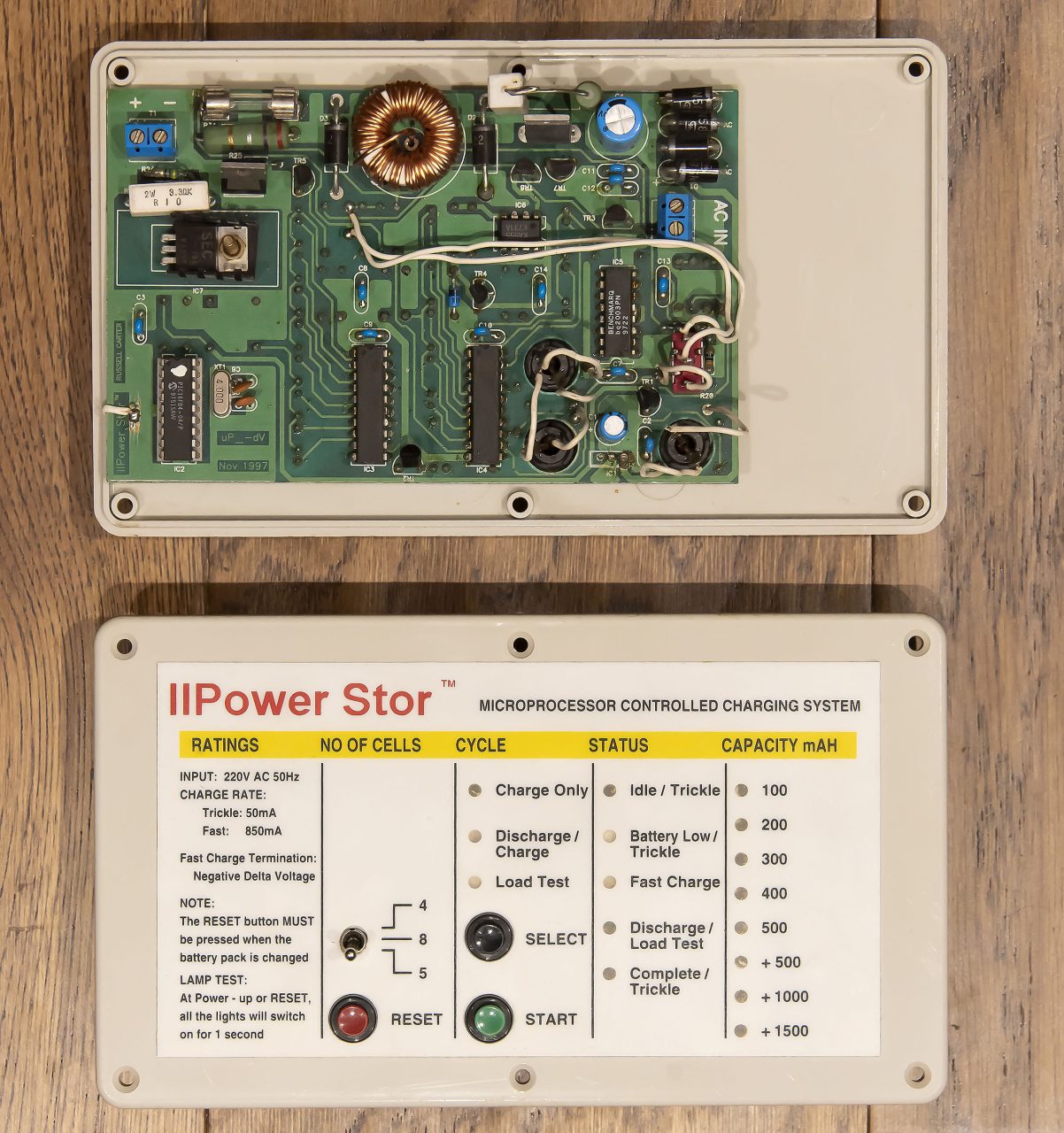
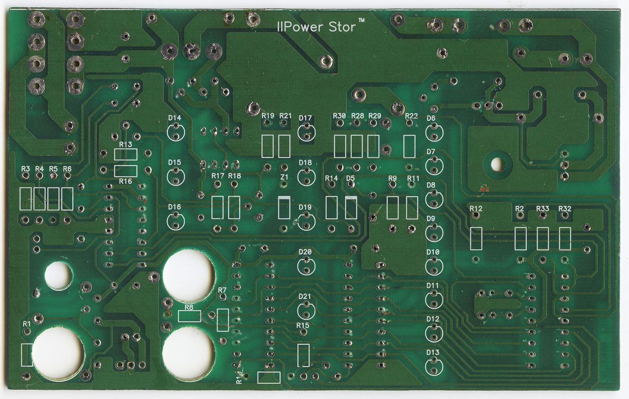
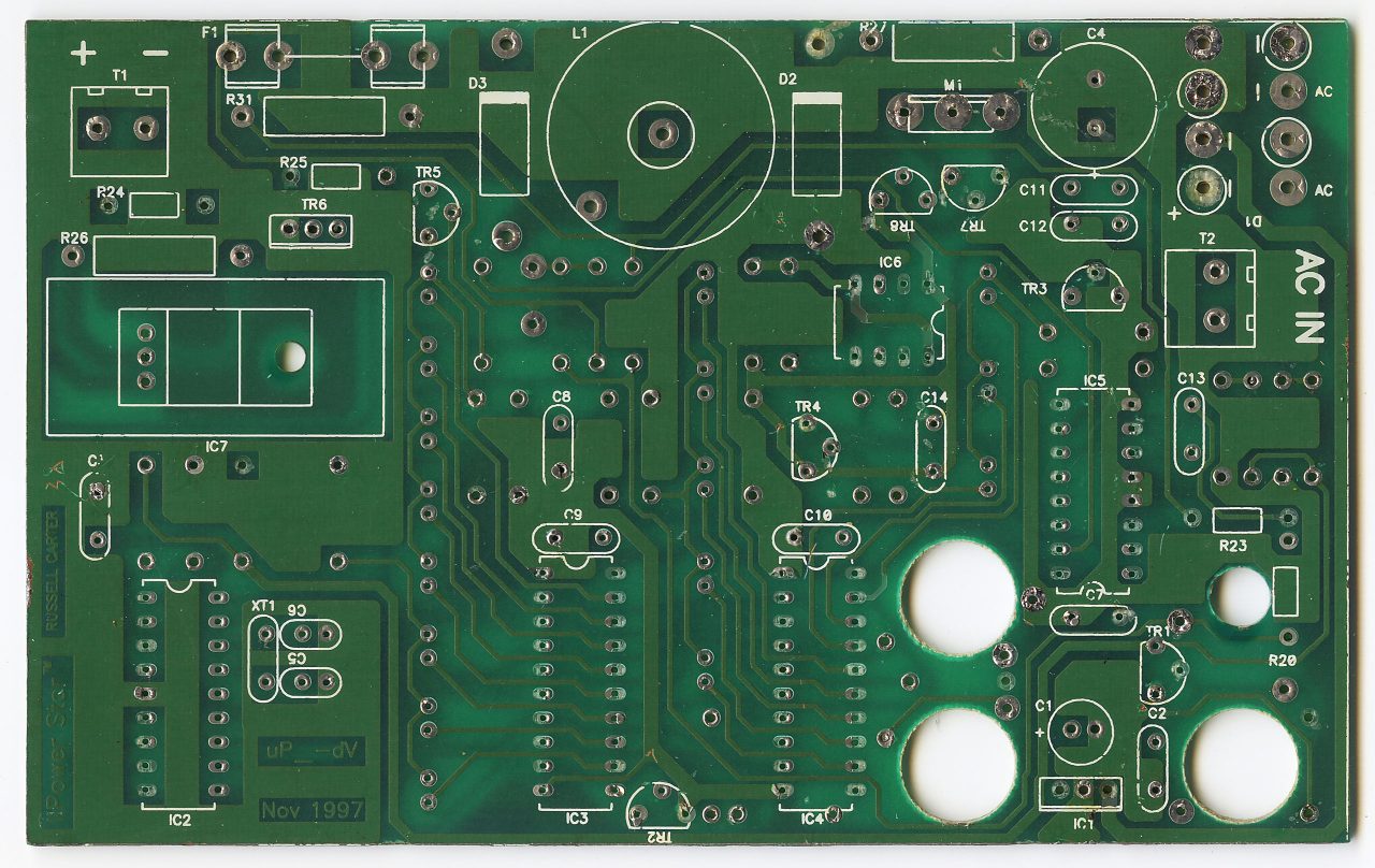
Construction was simple. The PCB was glued to he top of an ABS box with the LEDs embedded within holes, to expose them through the silk screened legend on the top. Pushbuttons were mounted on the lid and the switch was mounted on the PCB. A Mains lead was brought in through the side and connected via a fuse to a transformer, which supplies AC to the PCB.
Gallery
Leave a Reply